Small investments with big dividends: A case study
- Jackie Olinger
- Apr 2, 2021
- 4 min read
Custom mechanical design and manufacturing solutions sounds all well and good, right? But a custom solution has to provide value—otherwise, you might as well have shopped off-the-rack.
At KTM, we want to make sure we’re providing added value to each client, so for years we’ve written internal case studies for many of our projects—a summary describing the background, the problem, and the solution we developed. We’d like to share some of those findings with you.
The first post in our case studies series appears below.
Movers and Shakers
Structures that move require a unique design and analysis solution. Every structure needs stability, but once movement enters the picture, stability becomes even more vital to make sure that moving structures don’t turn into shaky ones. In most cases where a fixture or structural assembly is used, movement isn’t a design concern. However, when a system requires a specific design that develops a cyclical loading pattern (like a turntable that spins), it’s important to consider the dynamic response. Static analysis alone isn’t sufficient. The design life—not to mention safety—of the structure could be compromised.

The Problem:
KTM Solutions was contracted to design a machine that operated in a dynamic environment. Specifically, the machine needed to manipulate a payload on 3 axes: it raised and lowered a turntable, tilted the turntable forward and back, and rotated a load on the turntable.
This motion presented both static and dynamic loading conditions. The static loads were the weight of the machine (including motors and other parts) and the weight of the product. The dynamic load was the rotating product, accounting for a small but reasonable eccentricity. The maximum dynamic frequency due to the rotating load was 2.5 Hz (150 rpm).
The KTM Solutions Approach:
On every project, KTM Solutions follows our internal Systems Engineering process, a four-phased approach that begins with firm requirements and culminates in the finished product. Although the Systems Engineering process is all inclusive, this case study only focuses on the analysis portion.

We began by developing a conceptual design using our 3D-modeling design software. Next, to account for the most crucial load points (starting with static load), we determined static envelope load cases for all modes of operation and sized all structural elements to satisfy static loading requirements. The next step was to check the preliminary design for resonant frequencies and stiffen it as necessary to bring the resonance comfortably above the dynamic operating frequency (in this case, 2.5 Hz) so that operating the machine wouldn’t create a dynamic response that could damage the machine or harm operators. Once we were confident that the operating frequencies wouldn’t cause instability, we could complete the final sizing, by simulating the frequency response at 2.5 Hz to quantify product vibration, member stresses, and anchor loading. Then we were ready to document our analysis as a structural report.
KTM Solutions’ mechanical and structural analysis combines traditional calculations following industry-accepted practice and Finite Element Analysis (FEA) techniques. When setting up the initial analysis, KTM engineers determine the most efficient path to accurate analytical predictions. In this case, KTM Solutions’ approach was to use FEA for static, modal, and frequency response evaluations.
KTM’s Solution and Results:
Following the approach documented above, KTM’s engineering staff completed traditional calculations and employed engineering judgment to develop the conceptual design and initial structural component sizing. Using physical properties of the conceptual design, our engineers developed a Finite Element Model (FEM). Since engineers seek to plan for the worst-case scenario, the model was used to complete an FEA of the worst-load-case configuration of the machine (which was in the raised and tilted configuration).
The FEA indicated that the design satisfied the static load requirements. Next, a modal analysis was completed to determine the lowest natural frequency and “mode shapes.” Taken together, these analyses revealed the operating frequencies where resonance would occur and showed whether the resonance was of structural significance. Structural resonance must be eliminated to avoid catastrophic failure of the machine.
The FEA, particularly the dynamic response, paid off. Although the initial design didn’t need any changes to satisfy the basic static loading requirements, the modal analysis revealed the following:
The lowest natural frequency occurred at 4.69 Hz, which is sufficiently separated from 2.5 Hz to keep the baseline design. The 4.69 Hz mode shape showed the machine flexing left and right (see Figure 1). Additionally, frequency response showed that the rotating load moved left and right about 0.180” in each direction and that the maximum anchor load was 1450 lbs. It further indicated that the frame of the machine was attempting to skew, as indicated by the stress concentrations at the nodes in Figure 2, and that additional bracing could improve stiffness.
Using the FEA results, our engineers chose to add some additional cross bracing, in the form of two channel braces, to stiffen the system (see Figure 4). They added the bracing to the FEM and completed a new FEA modal analysis, which presented the following results:
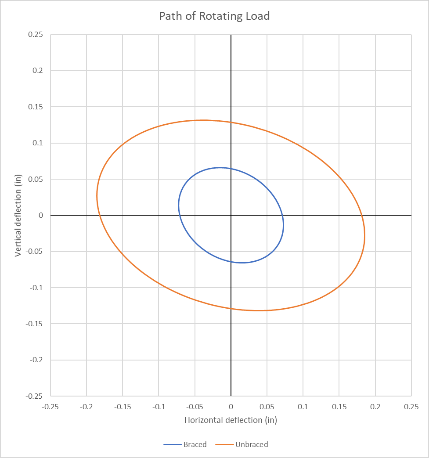
The first mode exhibited a similar shape as before, but the lowest natural frequency rose from 4.69 Hz to 5.52 Hz. Frequency response showed that the rotating load moved left and right about 0.073” in each direction (about a 50% reduction), and the maximum anchor load was reduced to 529 lbs., only a third of the first analysis (see Figure 5). Additionally, the frame members demonstrated drastically reduced stress (see Figure 3 and Figure 6), and the path of the rotating load showed less motion (see Figure 7; the braced configuration is the inner circle in blue).
The Takeaway:
With static analysis alone, especially when rotational loads are present, it’s possible to miss important aspects of the machine response that could affect the machine life and operational safety of a structural system. In the case of this project, the FEA results drove minor design changes that provided a significant benefit. These changes reduced member stresses and anchor loading. The reduced member stresses, particularly considering the cyclical loading of the system, will yield better fatigue life, and reduced deflections will improve the overall performance of the system. Minor changes helped ensure that this moving structure will be able to do its job more safely, and for a longer time.


Comments